How does a mirror decide which part of a room you can see?
A mirror does not display one fixed picture for everyone standing in front of it. Move your eye and a different set of light paths can reach you. Yet the apparent location of a reflected point remains orderly: for an ideal flat mirror, it lies the same perpendicular distance behind the surface as the original lies in front.
The image stays put while the path to it changes.
Measure angles from the normal
The law of reflection compares the incoming and outgoing angles to the normal, a line perpendicular to the mirror. In ideal specular reflection, those angles are equal. Measuring from the surface instead gives complementary angles, so stating the reference prevents an otherwise easy confusion in a ray diagram.
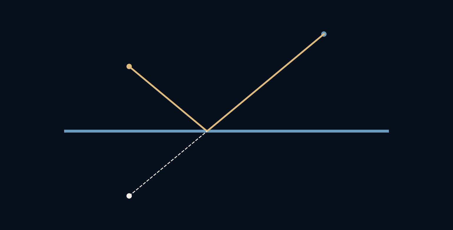
Our mirror lies along the horizontal line y equals zero. The light source is at coordinates minus three, two, and the eye is at three, three. Both sit above the surface. We seek the point on the mirror where a ray from the source can reflect into the eye, using uniform surrounding material and straight-line propagation.
Tracing a line backward from the eye is a calculation technique, not a claim that the eye emits the light being seen. In this reversible geometric setup, the same path can be checked in either direction. Keeping that distinction clear is helpful when a drawing includes both solid physical ray segments and dashed virtual extensions. Only the reflected segment in front of the mirror needs to reach the observer; the extension locates the apparent source.
Reflect the source before tracing the ray
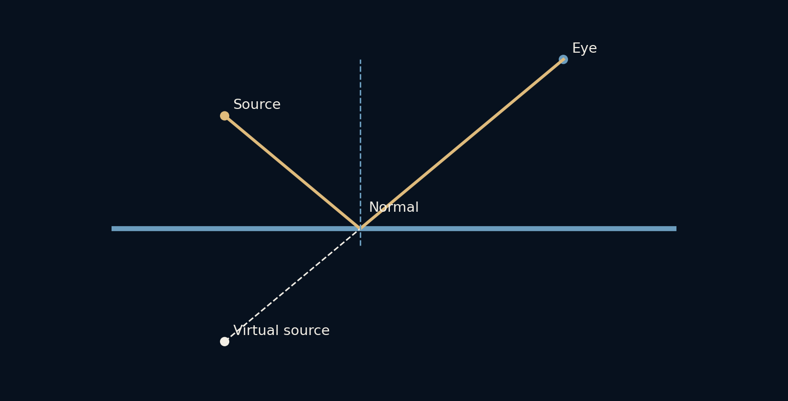
A convenient construction places a virtual source at minus three, minus two, directly opposite the real source across the mirror. Draw a straight line from this virtual point to the eye. It intersects the mirror at x equal to minus 0.6. Connecting the real source to that intersection gives the required incoming ray.
The script verifies the reflected direction with the vector reflection formula and finds an angle of about 50.19 degrees to the normal on each side. The dashed line behind the mirror is a geometric extension. Light does not need to travel through the mirror to that point for the eye to interpret the outgoing ray as coming from it.
The phrase ‘the same distance behind the mirror’ means perpendicular distance to the plane. It does not mean the image is the same distance from every observer. Our virtual point stays two units below the mirror, but its straight-line distance to the eye at (3, 3) is the square root of 61. Moving the eye changes that distance and the viewing direction without moving the virtual point or requiring a different reflected object.
The shorter-path view explains the same point
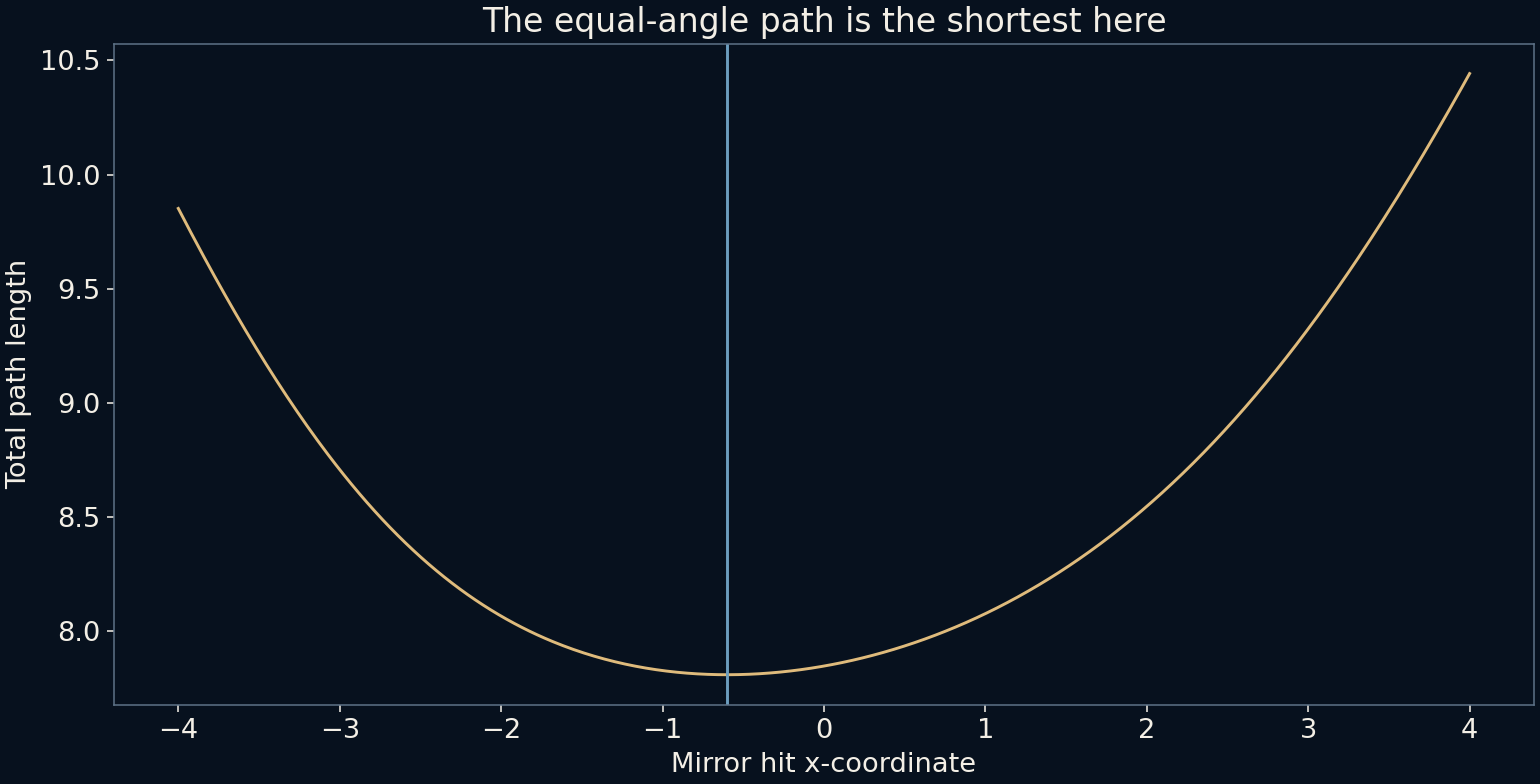
For this flat mirror and uniform propagation speed, the correct broken path also has the shortest total length among paths that touch the mirror once. Reflecting one endpoint turns that broken route into a straight line, making the geometry easier to see. The calculated length is about 7.810 distance units.
The path-length graph tries other hit positions along the mirror. Its minimum occurs at the equal-angle point. This is a restricted example of the stationary optical-path idea, not a claim that every optical arrangement simply chooses the shortest geometrical route. Refraction, multiple interfaces and more complex paths require their own optical treatment.
Move the eye, not the virtual object
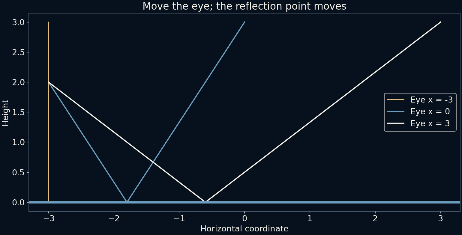
The final diagram moves the eye horizontally while keeping its height and the source fixed. Each position uses a different point on the mirror. The virtual source remains at the same reflected coordinates. This is why the reflected scene can behave like a stable space behind the surface even as the rays entering your eye change.
A finite mirror adds a visibility condition: the required reflection point must lie on the actual reflective area. Move far enough and that point can fall beyond an edge, making the object disappear from view. The mirror need not change the virtual image location for its frame to stop admitting the necessary path.
Reversal has a particular direction
The coordinate construction reverses the component perpendicular to the mirror while preserving coordinates parallel to it. In our two-dimensional example, the y coordinate changes sign and x does not. This is more precise than saying a mirror universally swaps left and right, which mixes the optical transformation with how we compare ourselves to an imagined person facing us.
Real mirrors can add complications. A reflective coating behind glass can produce faint additional reflections, while curved surfaces change the relation between object and image. Rough surfaces scatter light across many directions instead of producing the single ideal reflected direction used here. Those effects are outside this clean plane-mirror geometry.
A convincing reflection needs consistent paths
In a drawing, a reflection can look wrong even if the mirrored object itself is beautifully painted. Its apparent position, the visible portion and the viewer's location must fit the same geometry. The virtual-source construction offers a concrete way to check those relationships before adding surface texture or dramatic lighting.
The useful habit is to treat a mirror as a constraint on rays rather than as a picture pasted onto a wall. Ask where the observer is, where the reflected point appears to be and whether the connecting line meets the mirror. The reflected world is persuasive because all of those answers cooperate.
A two-dimensional sketch checks one cross-section, so passing it does not establish visibility through a real rectangular mirror. A three-dimensional construction must also put the intersection inside the top and bottom edges and account for anything blocking the path. Nevertheless, the same sequence survives: reflect the source across the plane, join it to the eye, then test the intersection against the actual mirror boundary. The boundary is part of the problem, not a decorative border added afterward.
Find the viewpoints that fit inside the frame
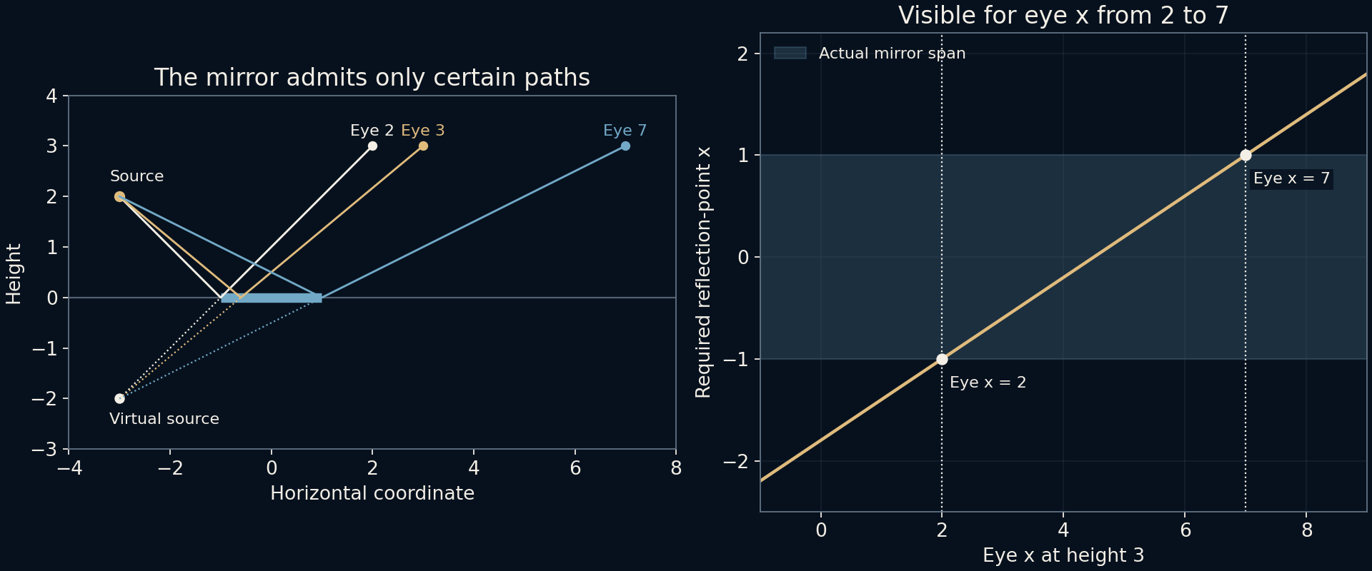
Give the mirror a definite size: let its reflective segment run from x = −1 to x = +1. Keep the source at (−3, 2) and let the eye move horizontally at height three. The straight line from the virtual source to an eye with horizontal coordinate e crosses the mirror at x = (2e − 9)/5. This one expression turns the verbal idea of moving beyond the frame into a testable visibility condition.
Requiring the hit position to stay between −1 and +1 gives eye positions from e = 2 to e = 7, including ideal boundary contact. At e = 3, the hit remains −0.6 and the point is visible. At e = 0, the required hit is −1.8, left of the mirror; at e = 8, it is +1.4, beyond the other edge. Those rays satisfy an infinite plane's geometry, but the finite mirror has no reflective surface where they need it.
The added illustration places the allowed mirror span beside the calculated hit-position line. It is a useful distinction for scene design: widening a mirror can admit additional viewpoints without changing the image's apparent depth, while moving the observer can change visibility without moving the image. This calculation treats the eye and source as points and ignores obstructions, glass thickness and reflection strength. A boundary hit is mathematically allowed here, but real frames and finite pupils need a more detailed model.
Further reading
OpenStax: Images formed by plane mirrors ↗OpenStax: The law of reflection ↗Original documentation and useful background.