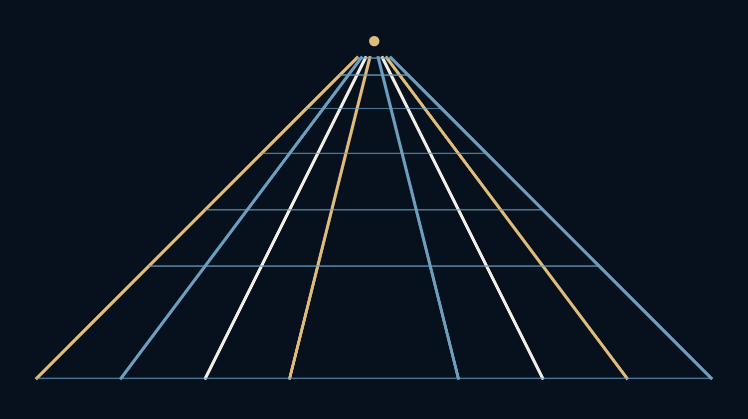
Why do railway tracks seem to meet when they never do?
A flat image must compress a three-dimensional arrangement into two coordinates. In a pinhole model, objects farther along the viewing direction occupy less image space. Parallel lines can therefore approach a shared point in the picture while remaining equally separated in the world. The apparent meeting is a consequence of projection.
A vanishing point is the image of a direction.
Divide by distance
Place an ideal camera at the origin looking along its depth axis. On a normalized virtual image plane, a point’s horizontal coordinate is X divided by Z, and its vertical coordinate is Y divided by Z. A focal-length factor would scale both. We use one so that the geometry stays easy to read.
The virtual plane represents an upright image in front of the camera. A physical pinhole forms an inverted image behind it, but the same perspective ratios apply after the usual coordinate convention. This article concerns those ratios rather than a real lens, sensor or camera assembly.
Two rails keep their real separation
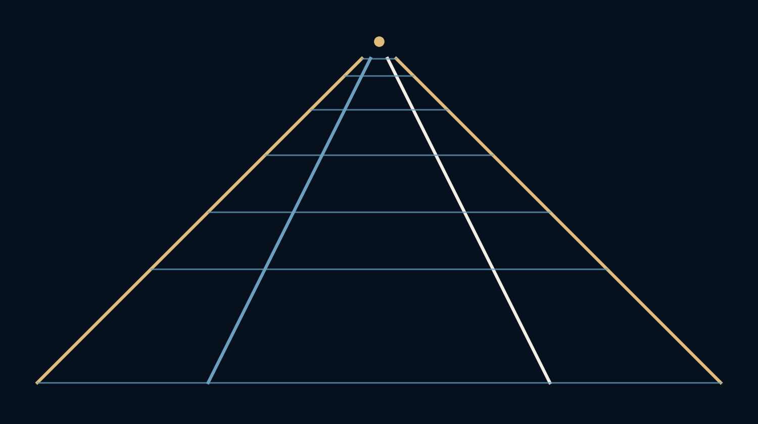
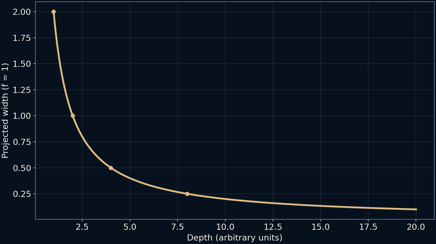
Our synthetic rails have horizontal world coordinates −1 and +1 and remain at a constant vertical coordinate of −1. Their depth increases away from the camera. At depth one, the image separation is two units. At depths two, four and eight, it becomes one, one half and one quarter.
The rails themselves never narrow. Only their projected separation changes. Crossbars placed at selected depths shrink for the same reason. The result resembles a familiar corridor or track scene, but every line in the picture comes from stated coordinates. No photograph has been measured or used to estimate a real distance.
The meeting lies beyond finite distance
As depth increases, the projected rail coordinates approach zero. They do not reach it at any finite depth in this construction. Their shared limit is the vanishing point. Extending the drawn image lines makes the convergence easy to recognize, even though the physical parallel lines have no shared endpoint.
This distinction matters in drawings. The vanishing point is a tool for organizing a family of directions. It is not an object sitting at the end of the road, nor proof that an actual road is straight. Curved lines, slopes and lens distortion can all complicate the interpretation of a real scene.
Change the direction, move the point
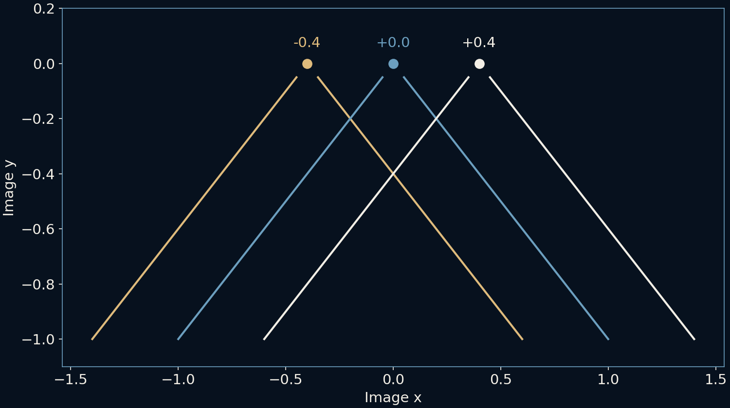
A second construction lets the rails drift horizontally as they recede. We set X equal to a starting offset plus a slope times Z. Dividing by Z gives the slope plus a shrinking offset. The vanishing horizontal coordinate therefore equals that slope in our normalized image.
The plotted slopes are −0.4, zero and +0.4, producing three distinct vanishing points. Each pair remains parallel in its own world direction. Parallel lines share a vanishing point only when they share that direction; a room can contain several families. Lines parallel to the image plane may remain parallel in the image instead of converging to a finite point.
A horizon is a collection of directions
For a level ground plane, its directions at infinity project onto a line that we call its horizon. Camera tilt moves that line within the image. Rotating the camera changes the projected directions as well. A vanishing point need not sit at the center of the frame or even inside the crop.
Architectural drawing often labels one-, two- or three-point perspective according to how the main families of edges are arranged relative to the view. Those labels are useful constructions, not a claim that every object has exactly that many possible vanishing directions. Arbitrary directions can have their own limits.
Use convergence as evidence, not certainty
Perspective can help align a drawn floor, place repeated objects or notice inconsistent geometry in an illustration. It is less decisive when a photograph contains curved surfaces, wide-angle distortion or a tilted ground plane. A plausible convergence does not identify a unique three-dimensional scene on its own.
The simple ratio still gives a strong reading habit: separate what stays fixed in the world from what shrinks in the projection. The rails keep their spacing; their image does not. Once that separation is clear, the apparent meeting stops being a visual paradox and becomes a compact record of the camera’s point of view.
Further reading
Physically Based Rendering: projective cameras ↗OpenCV: pinhole camera model ↗Original documentation and useful background.